Preparation

Figure 1 is a photograph of black woollen tell-tails on a board mounted vertically above the test vehicle at 90 km/hr .
The leftmost column of tell-tails shows a significant updraft over the front of the vehicle. The test-rig for the wings was therefore re-positioned rearward 300mm and upward 50mm to align the wing leading edge with the second column approximately.
The top tell-tails should be ignored because they are strongly influenced by flow across the top of the board. One can align the board, but only God can align the wind.
Of course this test procedure will never be perfect, but they say beggars can’t be choosers.
Test Rig
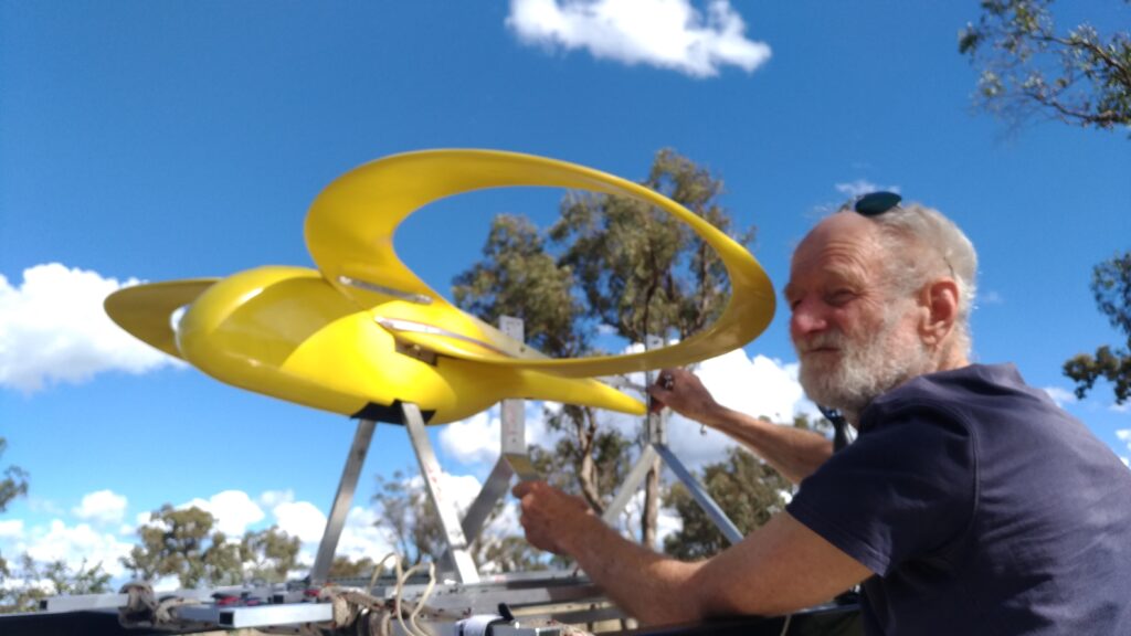
Figure 2: shows the wings mounted on a temporary body attached to car-roof rig with 4 load-sensors & anemometer. The 4 load-sensors are mounted on a pair of horizontal ball-bearing slides, so that all rearward drag is borne by a link at wing-level (see at position of Don’s right hand). The purpose of this arrangement is to record wing pitching moment independently of drag. The vibration of the car has the unexpected benefit of eliminating any slide frictional bias. Aerodynamic drag is therefore not recorded.