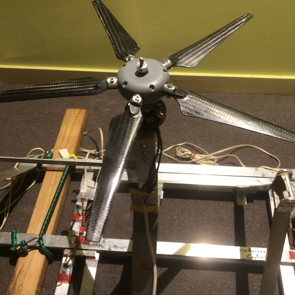
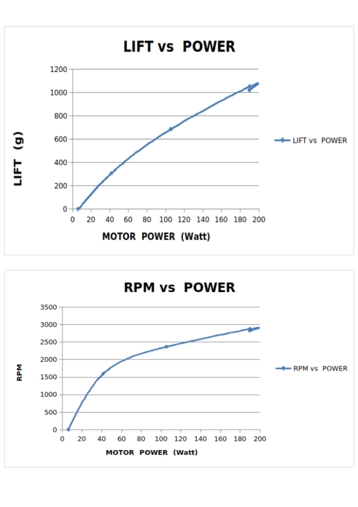
5-bladed rotor: initial test data
See a video of this test at https://www.instagram.com/agileaircraft/
The advantages of this 5-bladed design are
1) Extremely quick response. A conventional drone must spin each rotor faster to get more lift, for example to counter a random wind gust.
A drone or aircraft with far quicker response could be used in new ways, such as very close to structures in windy conditions.
2) Low vibration in forward flight. Each lift-rotor blade generates more lift when advancing than when retreating, but in a 5-bladed design, the forces cancel.
3) Low noise. For the same lift and diameter, 5-blades run slower and consequently quieter than 2-blades.
4) Auto-rotation by default. For safety and simplicity, the default blade pitch is negative when not powered. The blade pitch range is readily adjustable to suit application requirements.
If you need these advantages for your application, we may be able to supply suitable rotors. Get in touch.
Mk2 2-bladed rotor test data:
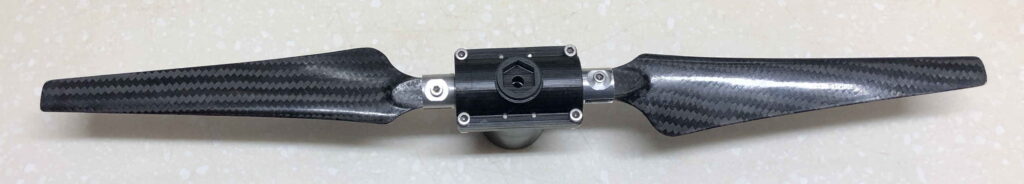
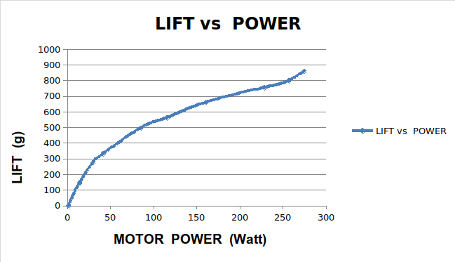
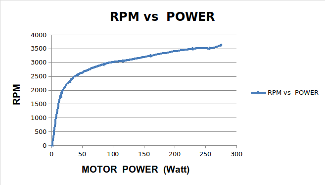
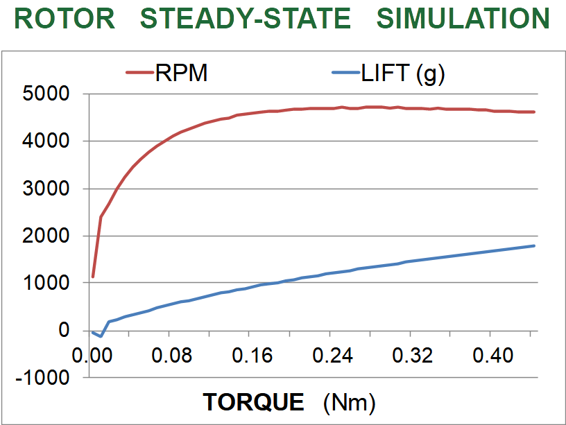
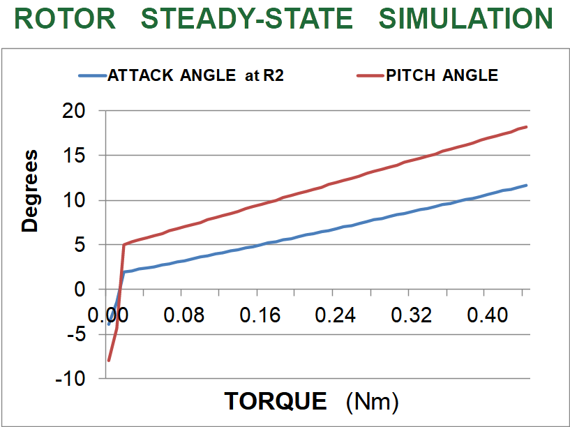
Figure 1 shows a simulation of the model rotor speed (RPM) and lift (grams) steady-states over a range of drive torques (Nm), using an (upublished) version of Blade-Element-Momentum-Theory (BEMT). This version approximates disk loading as a constant over an effective annulus. It conserves total angular momentum at the cost of another (possibly obscure) assumption.
The behaviour shown is for carefully selected values elastic-element tailoring. Other values can result in quite different behaviour.
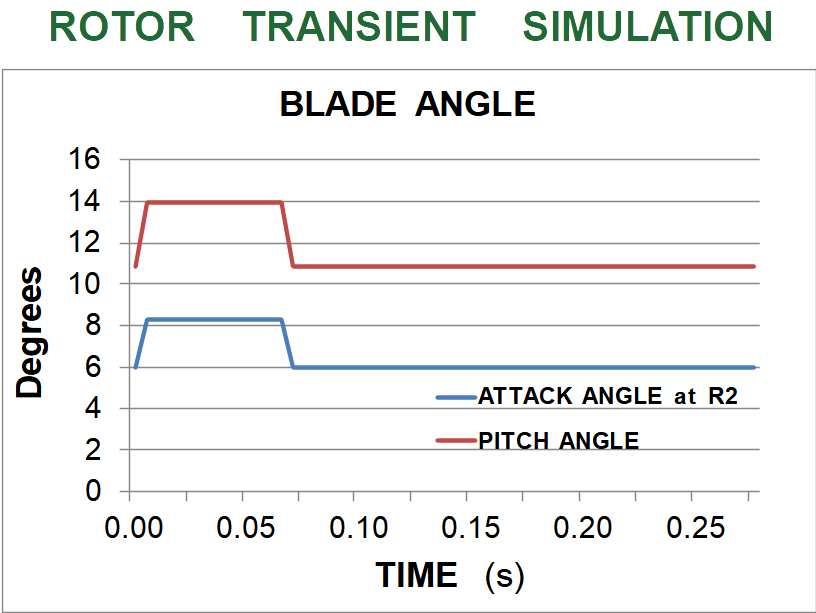
Figure 2 shows blade-pitch and angle-of-attack (at the tip) for the same simulation as Figure 1 .
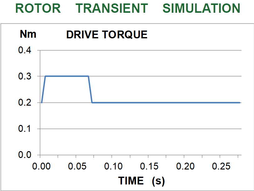
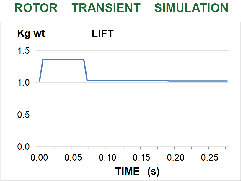
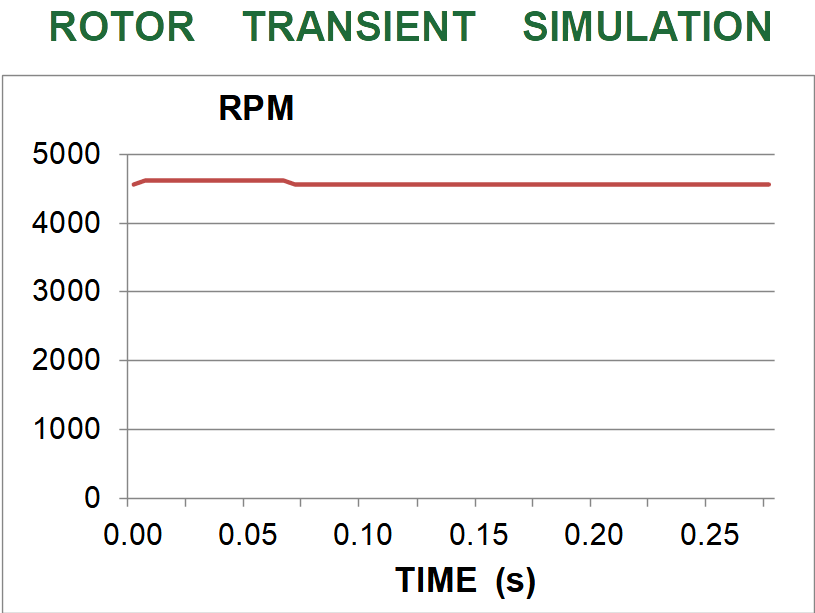
Figures 3-6 show simulated transient behaviour for a drive torque excursion event, where aerodynamics are here approximated as a sequence of steady states. Because the starting torque of 0.2 Nm is within the range where rotor speed is approximately constant, the change shown in Figure 6 is small, with an imperceptable spin-down after the event.
The Mk1 2-bladed rotor
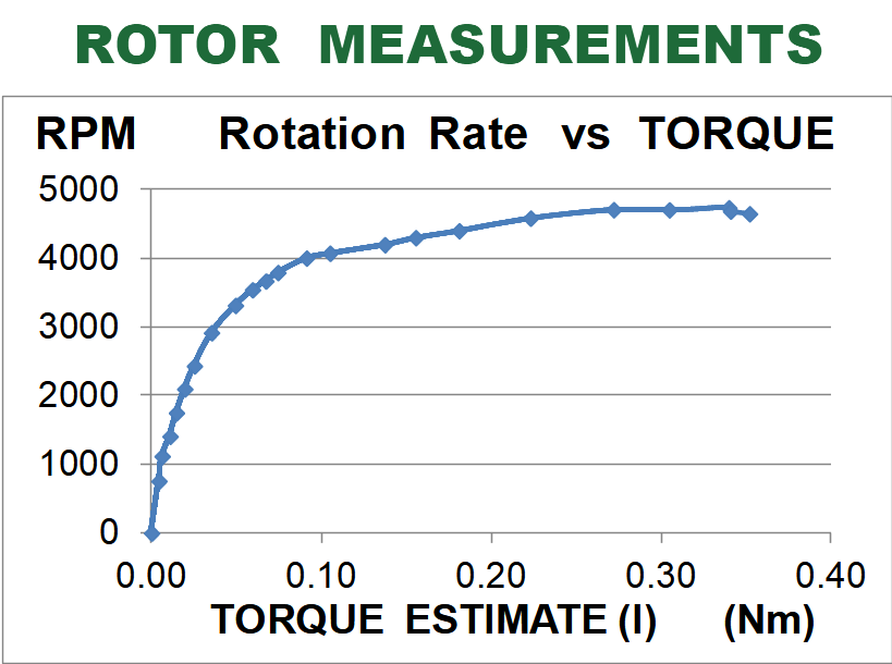
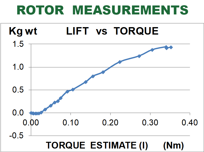
Figures 8 and 9 show rotor speed and lift at torques estimated from the motor current. Since the motor was never driven at more than half-power, it is thought that this will be a good estimate. The experimental behaviour has the same character as simulated. Other simulations show that different elastic parameters could have rsulted in very different behaviour.