The design is based on the premise that the rotational inertia of even a lightweight carbon-fibre rotor is at least 10 times that of the motor, but that the inertia of pitching blades plus pitch control mechanism can be less than the inertia of the motor.
Like [2], [4], [5], this design provides a simple pitch control mechanism by coupling blade pitch to rotor drive torque by means of elastic stack components that have a tailored elastic torsional response. This design does not require any additional connection between aircraft and rotor. It requires only drive torque supplied by a motor to rotor via a rotor shaft. However, [2] is designed to optimize performance over a wide range of advance-rates at constant torque. This is a very different from objectives 1A and 2A.
Unlike [2], this design provides a collective blade pitch control mechanism that operates in the opposite sense: Instead of a default coarse pitch which is reduced toward fine pitch by drive torque from a motor as in [2], this design sets a default negative or fine pitch, which is increased toward coarse pitch by drive torque from a motor. Simulation and experiment demonstrate that it can be configured to drive a lift-rotor at near constant rotation rate when hovering, even while the lift-rotor is driven with a wide range of torques to generate a wide range of lift thrusts.
In the event of loss of power, roll control is available by reducing lift on the appropriate rotor. Lift can be reduced by braking the rotor, which will set an even more negative blade pitch, and slow that rotor.
Electrical reaction by the drive motor is probably the simplest method of braking if there is a reliable method of either dumping energy, or transferring energy to the opposite rotor. Failed batteries might not provide enough electrical reaction to charging. Alternatively, a disk brake could be used.
Examples
(may be patent protected)
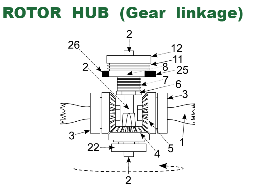
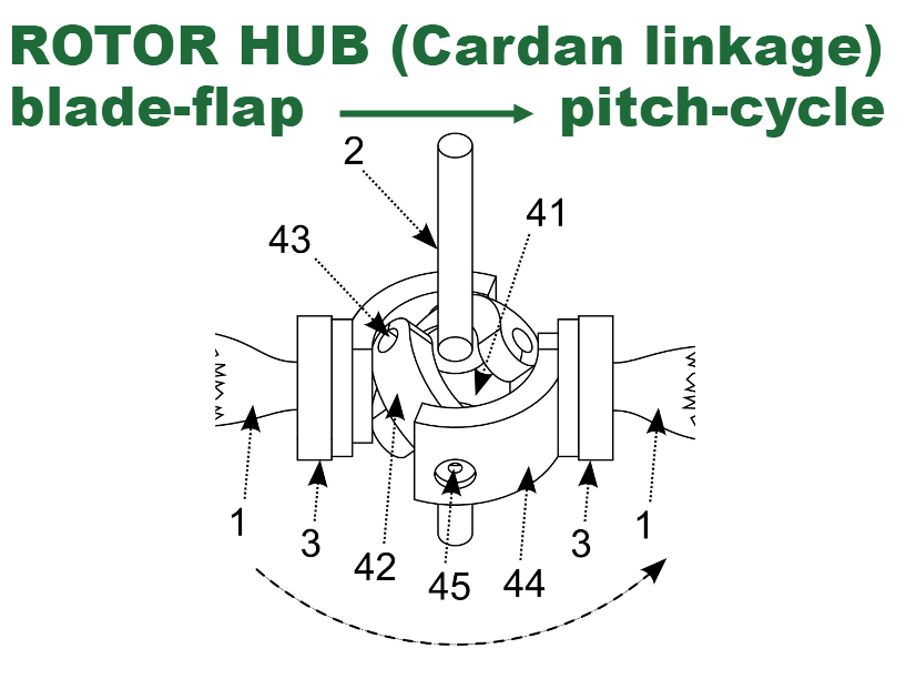
Figure 2a shows an elastic stack which includes two laminated elastomeric bearings (11 and 7) such that the collective pitch is negative when unpowered, but transitions to positive pitch as torque is increased.
Drive shaft 2 can turn freely inside bearing 22, plate 6, laminated elastomeric bearing 7, plate 8, and laminated elastomeric bearing 11, but is locked to drive plate 12. Plate 6 is mechanically locked to the rotor hub. Drive shaft 2 may transmit drive torque to turn rotor blades 1 via drive plate 12, to laminated elastomeric bearing 11, to second drive-plate 8, to laminated elastomeric bearing 7 to plate 6, to the rotor hub that transmits torque to rotor blades 1 while also allowing change of collective pitch. Part of any torque on drive-plate 8 may be transmitted to the rotor hub via teeth 25 and 26 when engaged with teeth 18 and 17, bypassing laminated elastomeric bearing 7 and plate 6.
Laminated elastomeric bearings 11 and 7 respond to increasing torque on drive shaft 2 with a tailored strain angle, causing bevel gear 4 to rotate relative to the rotor hub, rotate meshed bevel gears 5, and consequently rotate rotor blades 1 to an increasing pitch angle
Figure 4 shows an alternative mechanical coupling, shown isolated from other components for clarity. This is a type of Cardan linkage, using skew rotation axes, in which obstructions that limit rotation of drive and driven shafts may be acceptable. By symmetry, changes of pitch are the same for all blades. Central body 41 is locked to drive shaft 2. Joints 43 connect body 41 to links 42, and joints 45 connect links 42 to levers 44 which turn blades 1 on bearings 3. If joints 43 and 45 are implemented by bearings with single axes of rotation, then the Cardan linkage is over-constrained, and free rotation requires that all components rotate about axes that pass through a common point (at the centre of body 41).
The performance of these designs is critically dependent on tailoring of laminated elastomeric bearings. For this project we use an (unpublished) version of Blade Element Momentum Theory, which provides a very quick approximation that is good enough to predict behavior of the rotor as elastic tailoring is adjusted. See results here.
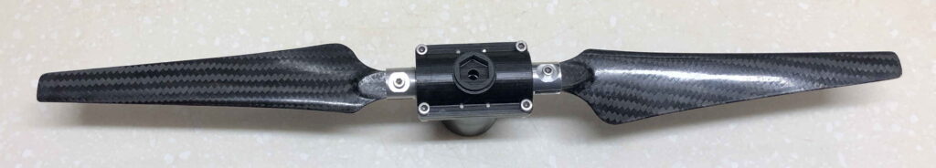
Prototype 16 inch 2-bladed rotor: